



文章目录
OPENPLC
- PLC(可编程逻辑控制器)起源于20世纪60年代,经历了从继电器替代到智能化控制的发展历程,成为现代工业自动化的核心设备。
- OpenPLC 是一个免费的开源 PLC 软件平台,允许用户在通用硬件(如树莓派、Arduino、工控机)上运行工业控制逻辑,遵循 IEC 61131-3 国际标准 ,此外还支持python、c++等扩展语言。

新建项目
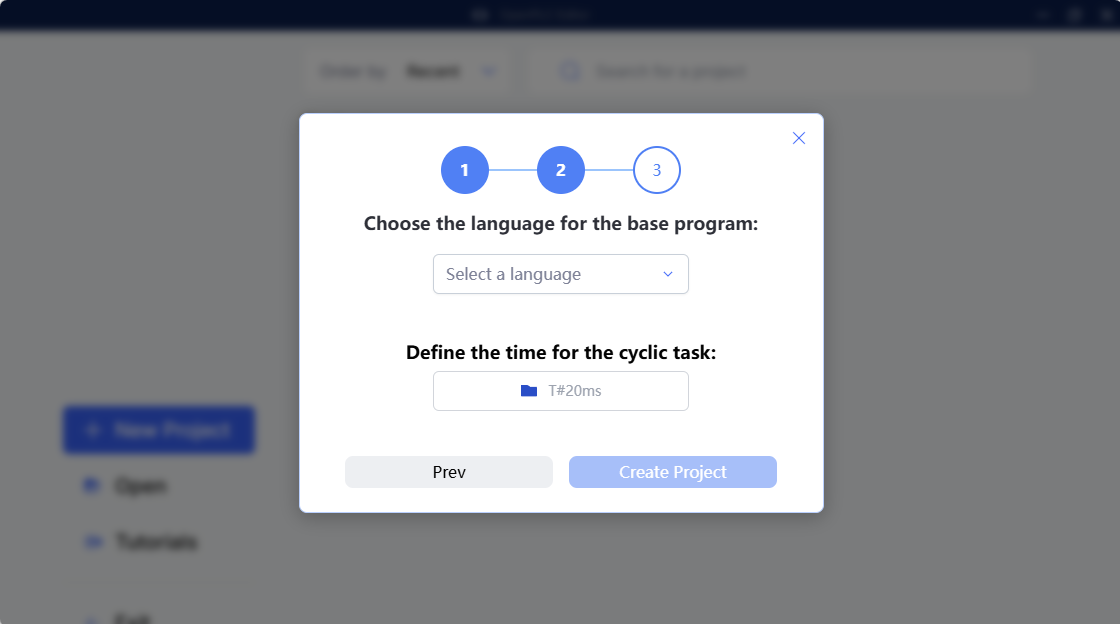
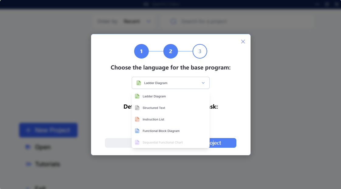
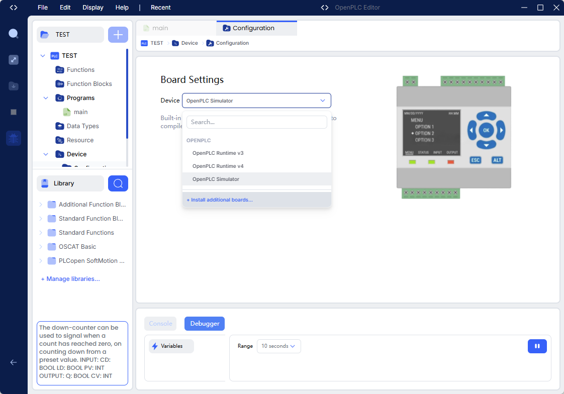
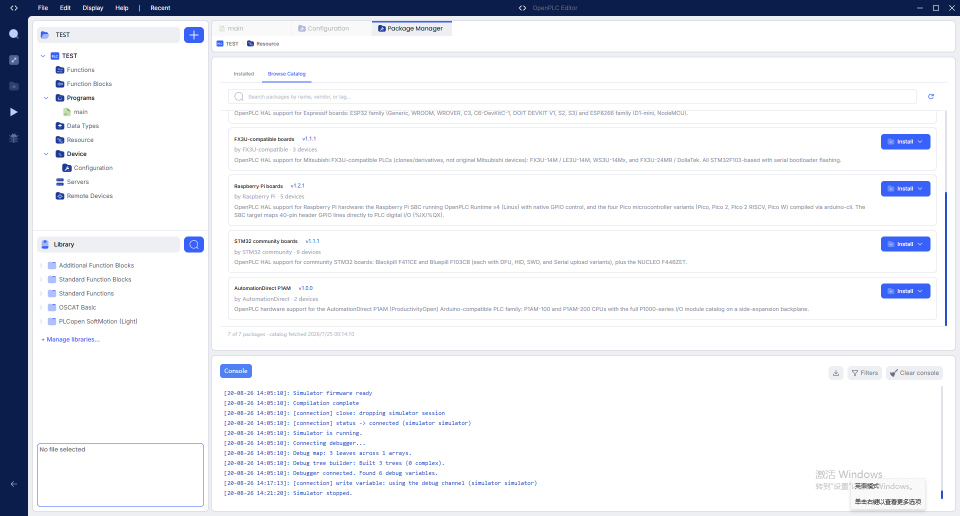
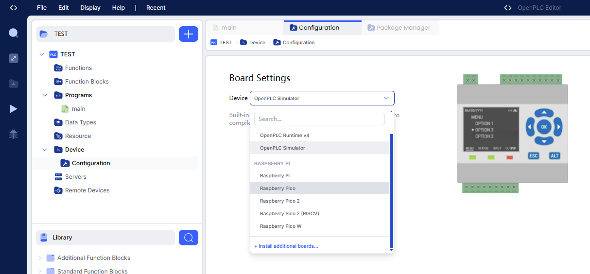
设备

变量 & 直接地址表示法
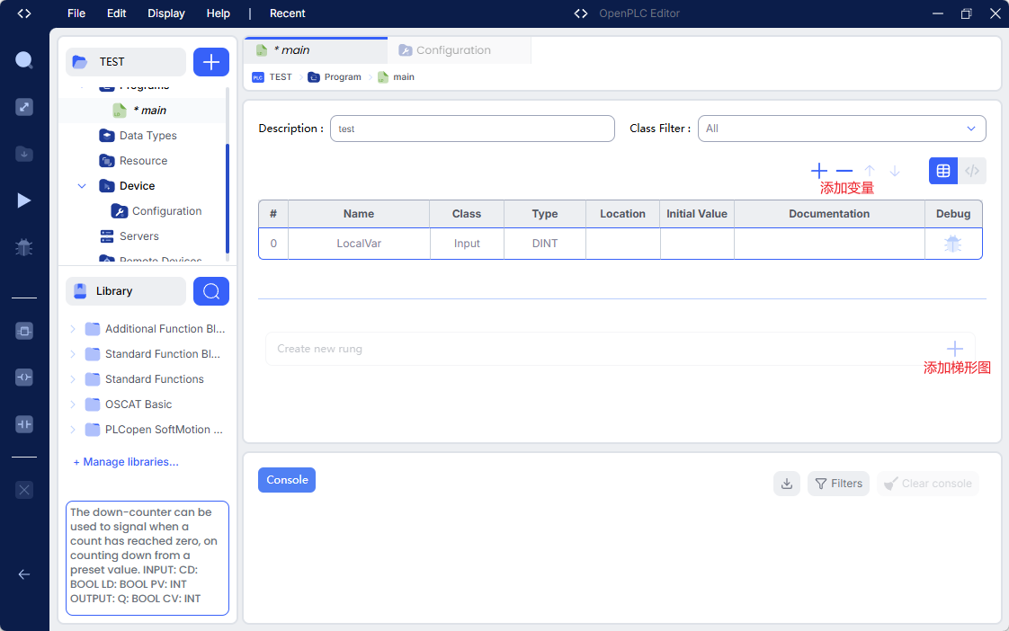
IEC 61131-3 的直接地址(Directly Represented Variables)
┌──────────────────────────────┐
│          PLC 地址空间         │
├──────────────────────────────┤
│                              │
│  Input                       │
│  %I                          │
│  ├── %IX                     │
│  ├── %IB                     │
│  ├── %IW                     │
│  └── %ID                     │
│                              │
│  Output                      │
│  %Q                          │
│  ├── %QX                     │
│  ├── %QB                     │
│  ├── %QW                     │
│  └── %QD                     │
│                              │
│  Memory                      │
│  %M                          │
│  ├── %MX                     │
│  ├── %MB                     │
│  ├── %MW                     │
│  └── %MD                     │
│                              │
└──────────────────────────────┘
-
在 PLC 编程软件(如 OpenPLC 编辑器)中,
Location(位置)字段的核心意义是为变量绑定具体的物理 I/O 地址或系统内部存储器地址。 -
填写了 Location:变量就和真实的物理世界(按钮、传感器、LED灯、继电器)打通了。例如,
StartButton为 1,PLC 就会自动去读取你绑定的那个物理引脚的电平状态。 -
留空不填:说明这个变量只是一个纯逻辑中间变量,只在程序内部进行计算,不去驱动任何物理硬件。
-
Location 的填写规则(遵循 IEC 61131-3 标准)格式通常为:
%+区域前缀+大小前缀+地址编号。%IX0.1(意思是:读取第0组第1个输入位的 1个Bit 信号)%MX0.0(意思是:使用内部存储区第0组第0个 1Bit 的空间)%QX0.13(意思是:向第0组第13个输出位的 1个Bit 写入信号)
% I X 0 . 0
│ │ │ │   │
│ │ │ │   └─ bit
│ │ │ └───── byte/位置
│ │ └─────── 数据宽度:Bit
│ └───────── Input
└─────────── Direct address
-
区域前缀(决定是输入还是输出):
I(Input):代表输入区域。用来接收外部信号,比如接在开发板引脚上的按钮、传感器。Q(Output):代表输出区域。用来驱动外部设备,比如接在开发板引脚上的 LED 灯、继电器、蜂鸣器。M(Memory):代表内部存储区。用于程序内部存储临时数据,不直接对应物理引脚(比如用来记录电机是否处于“启动”状态的中间标志位)。
-
大小前缀(决定数据类型):
X(Bit):1位(最常用,就是 ON/OFF,0/1,对应BOOL类型)。B(Byte):8位。W(Word):16位。D(Double Word):32位。
- 具体 bit 编号方式还要结合具体实现/硬件映射确认,但 IEC 的直接地址表达就是这种层级结构。
- OpenPLC Physical Addressing Guide
- https://old.autonomylogic.com/docs/2-6-slave-devices/
- https://autonomylogic.com/docs/2-5-modbus-addressing/
触点
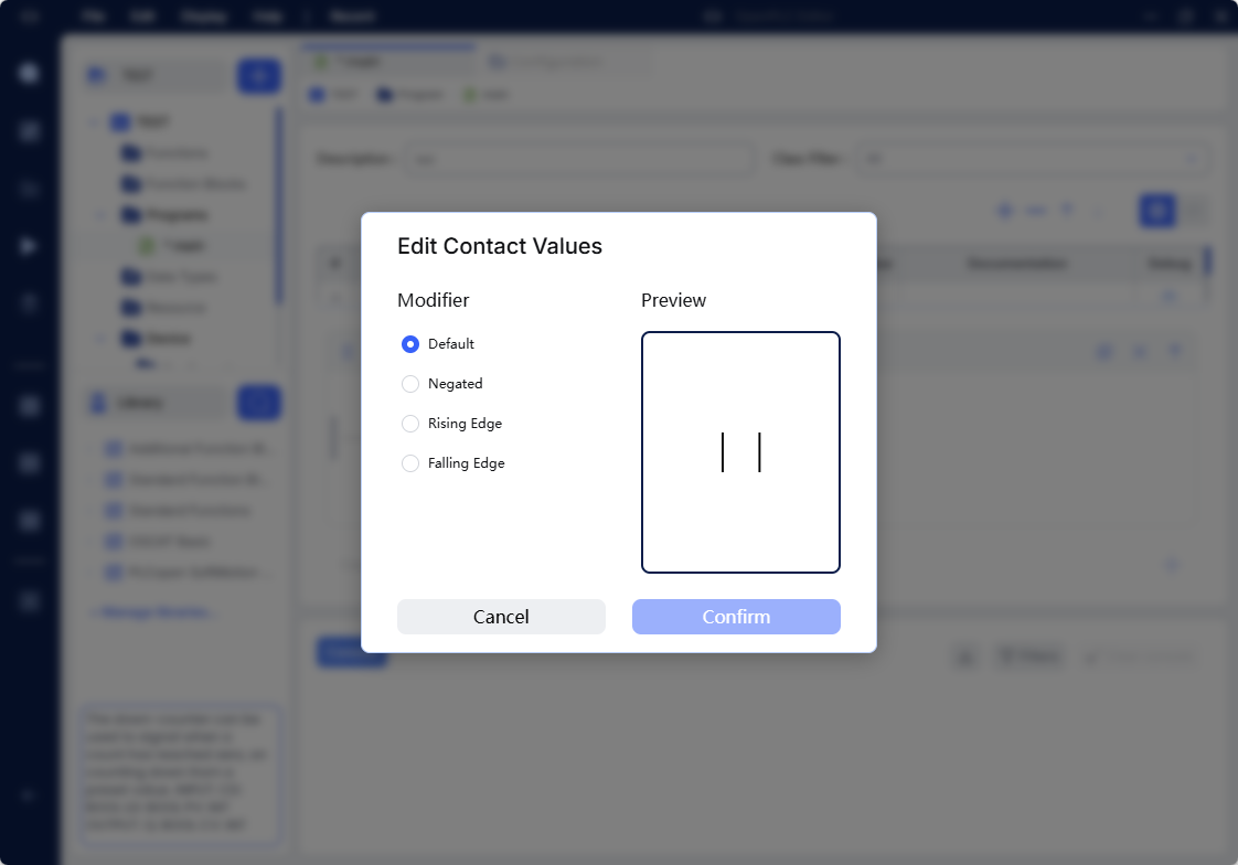
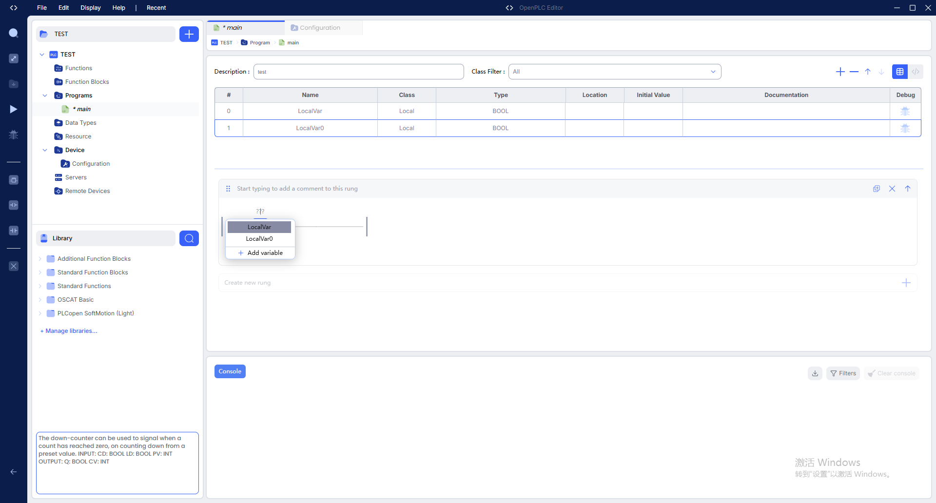
| 对比维度 | 常开触点 (Normally Open, NO) | 常闭触点 (Normally Closed, NC) |
|---|---|---|
| 定义(常态) | 在没有任何外力作用、设备未通电时,触点处于断开状态。 | 在没有任何外力作用、设备未通电时,触点处于闭合状态。 |
| PLC 梯形图符号 | ∣ ∣ || ∣∣ | ∣ / ∣ |/| ∣/∣ |
| 逻辑状态 | 常态为 FALSE(假/0),触发后变为 TRUE(真/1)。 | 常态为 TRUE(真/1),触发后变为 FALSE(假/0)。 |
线圈
| 功能 | 中文 | 作用 | 触发条件 | 输出特点 |
|---|---|---|---|---|
| Coil | 普通线圈 | 直接输出逻辑结果 | 条件为 1 | 输出 = 1 |
| Negated Coil | 取反线圈 | 输出逻辑结果的反值 | 条件为 0 | 输出 = 1 |
| Rising Edge | 上升沿 | 检测 0 → 1 的瞬间 | 信号上升 | 通常产生一个扫描周期的脉冲 |
| Falling Edge | 下降沿 | 检测 1 → 0 的瞬间 | 信号下降 | 通常产生一个扫描周期的脉冲 |
- Falling Edge = 检测信号从 1 变成 0 的瞬间。 只有发生1 → 0的瞬间,下降沿检测才会产生一个 ON 信号。
- 例如 PLC 扫描过程中,只有在下降沿发生的那个扫描周期:Falling Edge = 1 ,其余时间:Falling Edge = 0 。
恒1
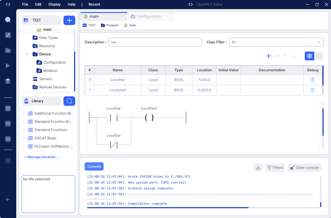
自锁(起保停)
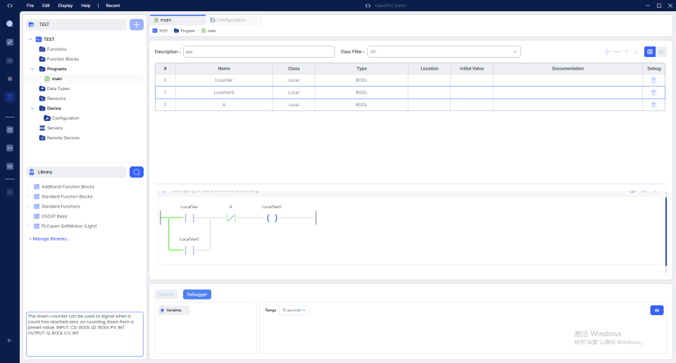
-
考虑锁定是可忽略A,A的作用是停止。
-
普通的按钮是“点动”的,手一松开,按钮弹起,电路断开,设备就会立刻停止。
-
按下启动按钮 → 电流经常闭 → 线圈 。
-
在 PLC 编程中,必须严格考虑“工作周期(扫描周期)”。PLC 的工作方式是 “串行循环扫描” ,也就是一个周期接一个周期地执行代码。一个完整的扫描周期通常包含三个阶段:
- 输入采样阶段:PLC 集中读取所有外部按钮的状态(比如启动按钮是 1,停止按钮是 0),存入内存。
- 程序执行阶段:PLC 从上到下、从左到右执行梯形图逻辑。
- 输出刷新阶段:PLC 将程序执行的结果统一发送给外部输出模块,点亮 LED 或驱动继电器。
- 所以,在 PLC 中,“保”(自锁)这个动作,必须跨越至少两个扫描周期才能真正生效
- 第 1 个周期:按下了启动按钮。PLC 在输入采样阶段读到启动按钮为 1。在程序执行阶段,PLC 发现启动按钮通了,于是把输出线圈(比如 Q0.0)置为 1。但是,此时程序已经执行完了,自锁触点还没来得及闭合。
- 第 2 个周期:松开了启动按钮(输入变为 0)。但在程序执行阶段,PLC 发现上一周期 Q0.0 已经是 1 了,于是自锁触点闭合,Q0.0 继续保持为 1。
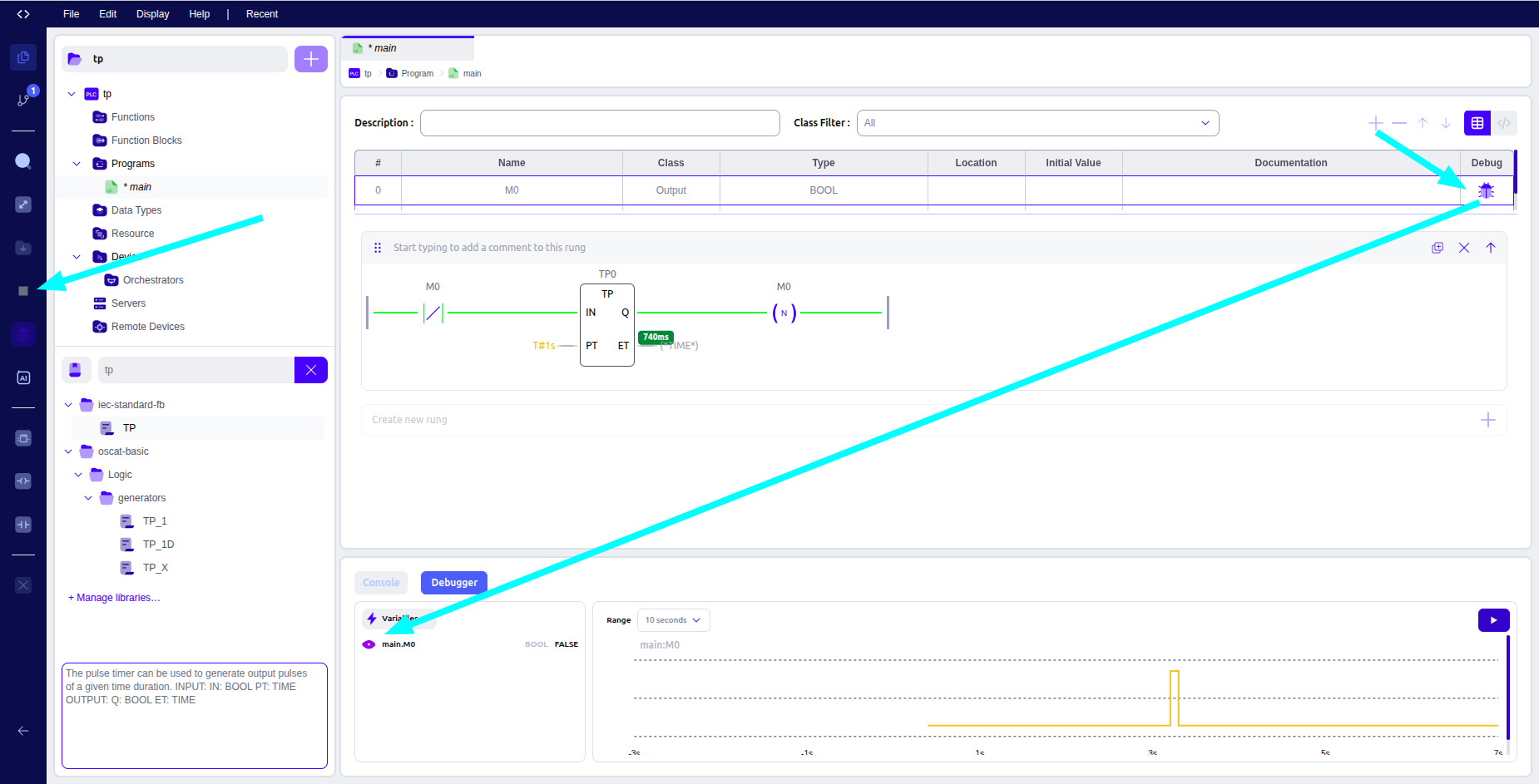
仿真
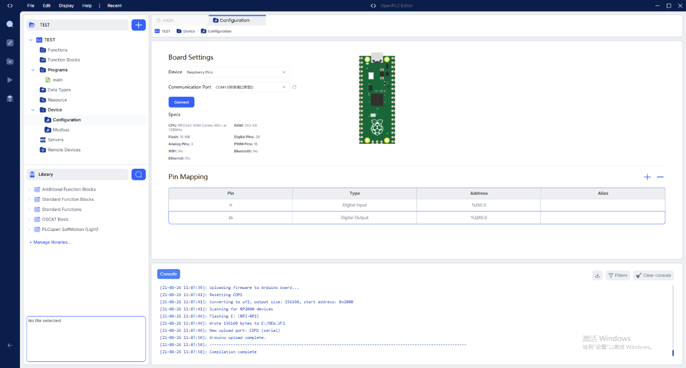
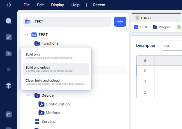
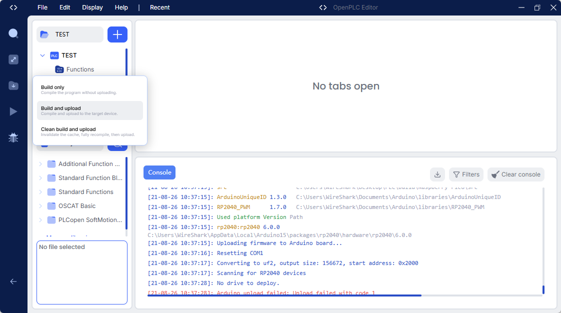
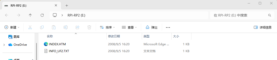
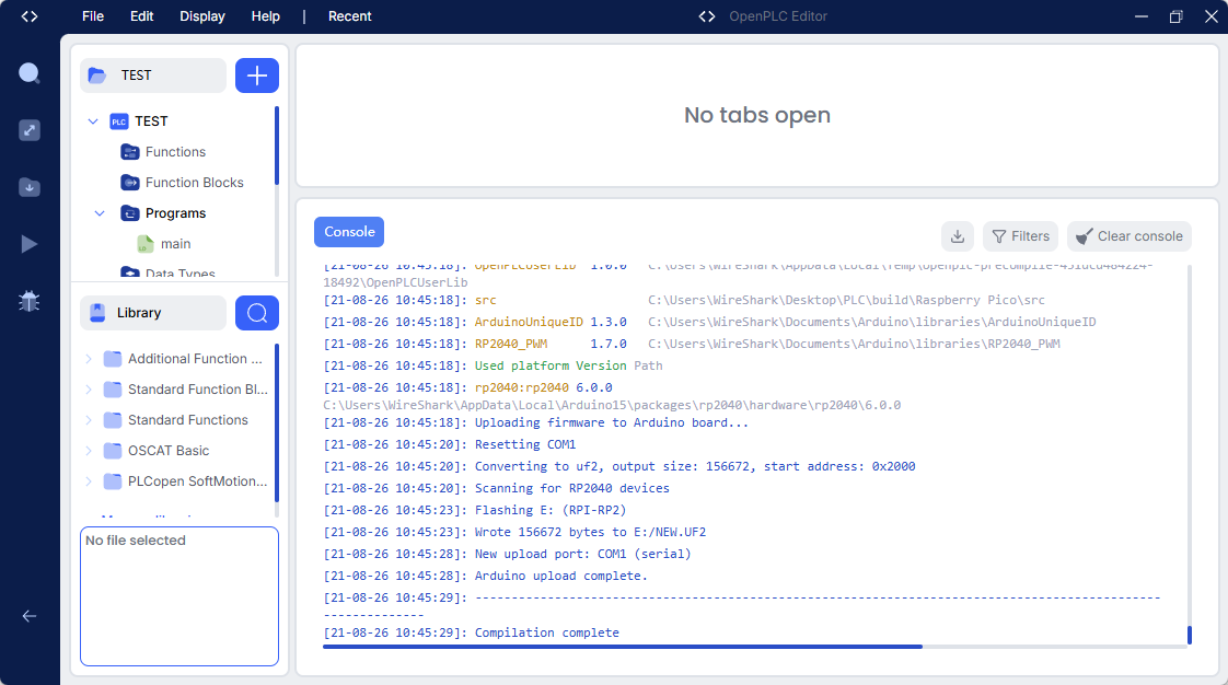
烧录
- 在OPENPLC中使用PLC语言写程序有点像运行跨平台语言,可以在不同的硬件上运行同一个程序。
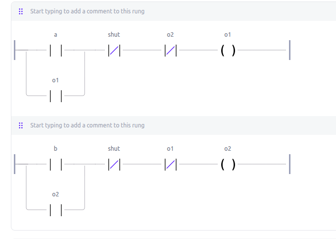
互锁电路
- 两个设备不能同时运行的场合:
定时器
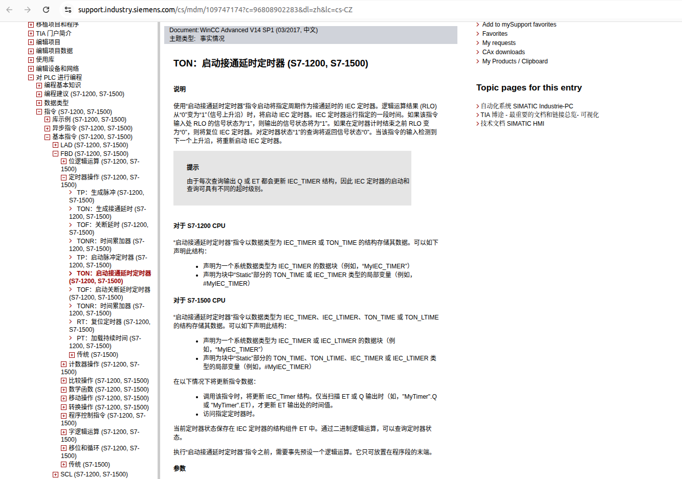
定时器指令整理:
| 序号 | 指令 | 中文名称 | 主要功能 | S7-1200 | S7-1500 |
|---|---|---|---|---|---|
| 1 | TP | 生成脉冲 | 输入信号上升沿触发,输出保持 PT 设定时间 | ✓ | ✓ |
| 2 | TON | 生成接通延时 | 输入保持为 1,经过 PT 后输出变为 1 | ✓ | ✓ |
| 3 | TOF | 关断延时 | 输入由 1 变 0 后,输出继续保持 1,经过 PT 后变 0 | ✓ | ✓ |
| 4 | TONR | 时间累加器 | 输入有效时累加计时,输入失效后可保留已累计时间 | ✓ | ✓ |
| 5 | TP | 启动脉冲定时器 | 启动脉冲定时器,产生固定持续时间的输出脉冲 | ✓ | ✓ |
| 6 | TON | 启动接通延时定时器 | 启动接通延时,输入持续有效达到设定时间后输出 | ✓ | ✓ |
| 7 | TOF | 启动关断延时定时器 | 启动关断延时,输入关闭后继续输出一段设定时间 | ✓ | ✓ |
| 8 | TONR | 时间累加器 | 启动累加计时功能,累计已经运行的时间 | ✓ | ✓ |
| 9 | RT | 复位定时器 | 将定时器复位,清除定时器当前状态/累计时间 | ✓ | ✓ |
| 10 | PT | 加载持续时间 | 为定时器加载预设的持续时间(Preset Time) | ✓ | ✓ |
快速记忆
| 指令 | 记忆方法 | 输出特点 |
|---|---|---|
| TP | 脉冲 | 输入触发 → 输出保持一段时间 |
| TON | 接通延时 | 输入开 → 延时 → 输出开 |
| TOF | 关断延时 | 输入关 → 延时 → 输出关 |
| TONR | 累加计时 | 时间可以累计保存 |
| RT | Reset Timer | 复位定时器 |
| PT | Preset Time | 设定/加载定时时间 |
注意:第 1~4 项和第 5~8 项本质上是同一组 TP、TON、TOF、TONR 定时器功能;区别主要在于具体调用/启动方式或指令环境。PT 是定时器的预设时间参数,不是一种独立的定时器类型。
TP示例:方波脉冲发生器/自激振荡电路
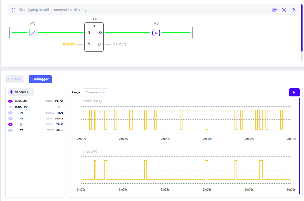
- 自激振荡电路:M0 会以固定节奏产生极短暂的 TRUE 脉冲(仅持续一个扫描周期),周期约为 100ms + 一个扫描周期。
💡 可以理解为一个简易的方波脉冲发生器,M0 每隔约 100ms 产生一次单扫描周期的脉冲。
-
从左至右依次为:
- 取反触点(M0,negated contact) — 当 M0 为 FALSE 时,触点导通
- TP 脉冲定时器块(TP0) — IN 输入由取反触点驱动,PT = T#100ms
- 下降沿线圈(M0,fallingEdge coil) — 检测 TP0.Q 的下降沿,并将结果写入 M0
-
运行逻辑(循环分析)
- 初始状态: M0 = FALSE
- 第1步: M0 为 FALSE → 取反触点导通 → TP0.IN = TRUE → TP0 开始计时
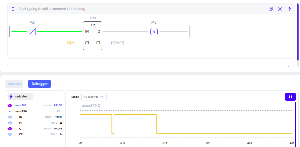
- 第2步: 计时 100ms 期间,TP0.Q = TRUE,下降沿线圈无动作,M0 保持 FALSE
- 第3步: 100ms 到达后,TP0.Q 从 TRUE → 下降为 FALSE → 下降沿线圈触发一个扫描周期 → M0 被置为 TRUE
- 第4步: M0 = TRUE → 取反触点断开 → TP0.IN = FALSE → TP0 复位,TP0.Q = FALSE
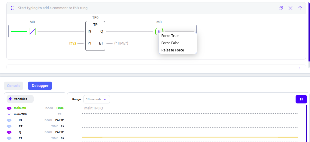
- 第5步: TP0.Q 已经是 FALSE,不再产生下降沿 → 下降沿线圈不触发 → M0 在下一个扫描周期回到 FALSE
- 第6步: M0 回到 FALSE → 电路从第1步重新开始
-
存在扫描时序依赖。在不同 PLC 运行时或实现环境中,可能表现出不同的重复触发行为
-
建议修改: 若需要稳定的周期脉冲,可改用 TON.
计数器指令
- 第九节:计数器指令
- 在 OpenPLC / IEC 61131-3 里,计数器指令主要用于对事件发生次数进行累计。最常见的是下面几个:
| 指令 | 全称 | 作用 |
|---|---|---|
CTU | Count Up | 加计数 |
CTD | Count Down | 减计数 |
CTUD | Count Up/Down | 加/减双向计数 |
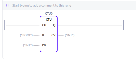
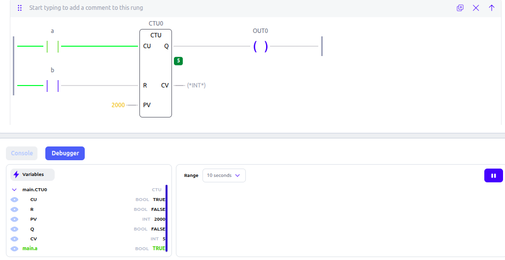
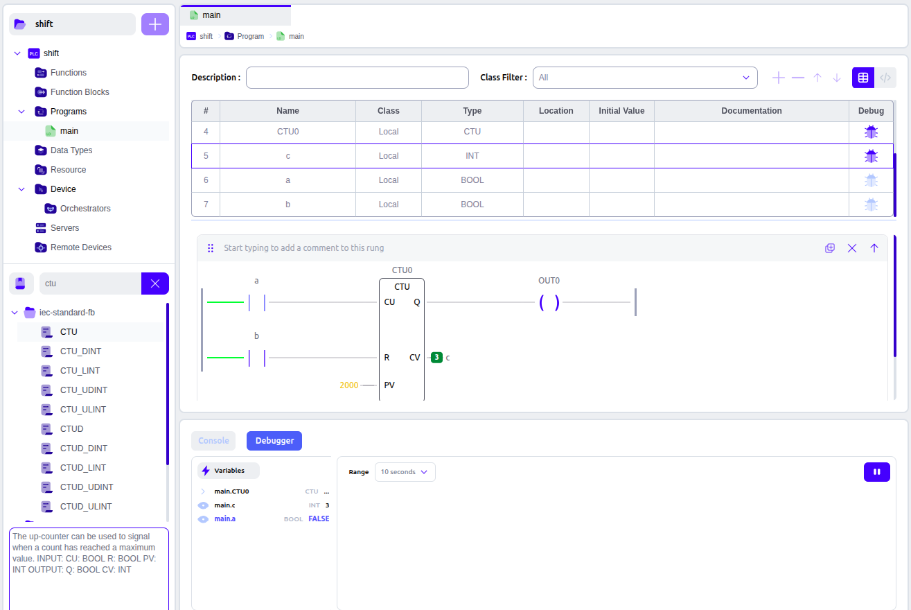
| 端口 | 类型 | 含义 |
|---|---|---|
CU | BOOL | Count Up,加计数输入 |
R | BOOL | Reset,复位 |
PV | INT | Preset Value,预置值 |
Q | BOOL | 是否达到计数目标 |
CV | INT | Current Value,当前计数值 |
MOVE
- 在 OpenPLC / IEC 61131-3 中,MOVE 是一个数据传送(赋值)功能块/函数,作用非常简单:把输入值 IN 复制到输出 OUT。
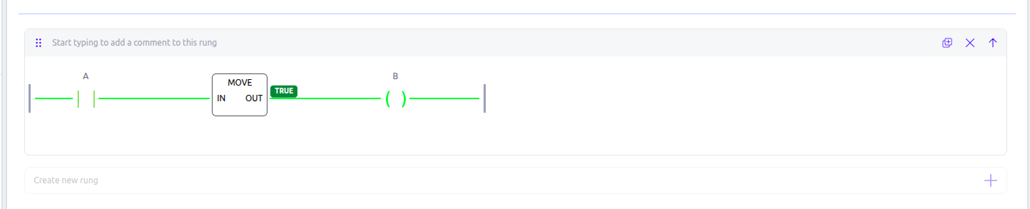
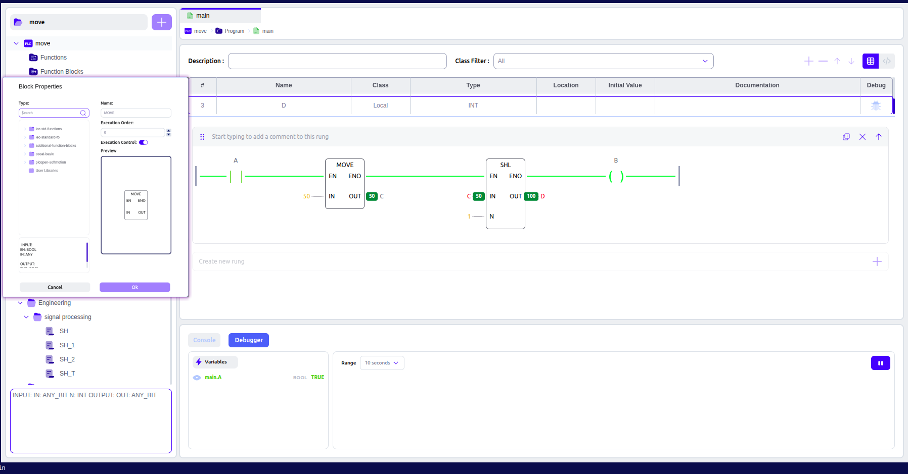
- MOVE可用于初始化变量:
移位寄存器
加減乘除




modbus
- OpenPLC Runtime 里的 Modbus/TCP Slave Server(从站服务器) 核心作用是让外部 Modbus TCP 主站(例如 SCADA、触摸屏、上位机、另一台 PLC)通过 TCP 访问 OpenPLC 中的变量。
- 外部 Modbus 主站 ⇄ TCP/IP ⇄ OpenPLC Modbus Slave ⇄ PLC 程序中的
%IX/%QX/%MW/%MD/...变量
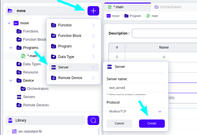
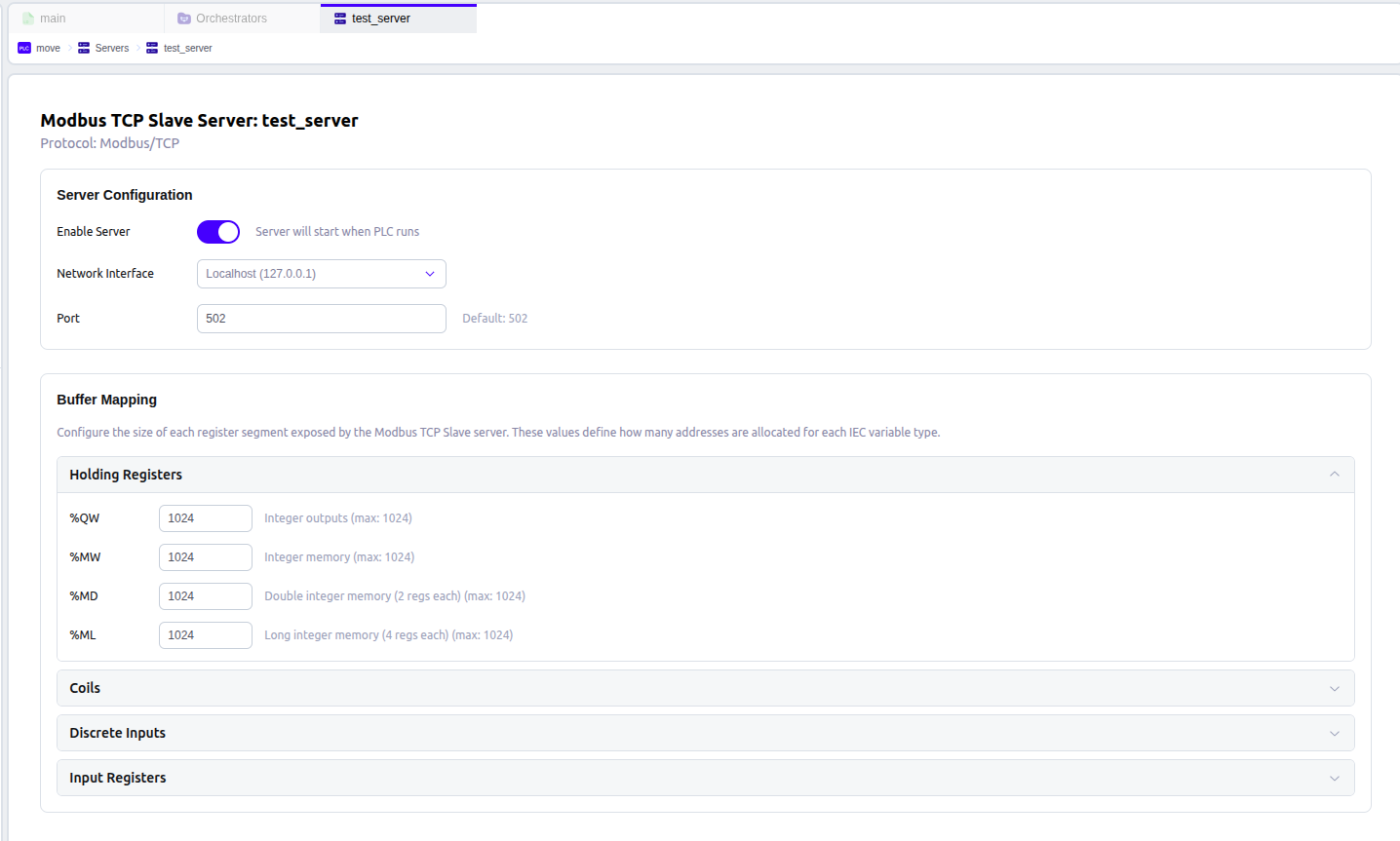
- 如果选择 127.0.0.1, Modbus Server 只监听本机回环接口。
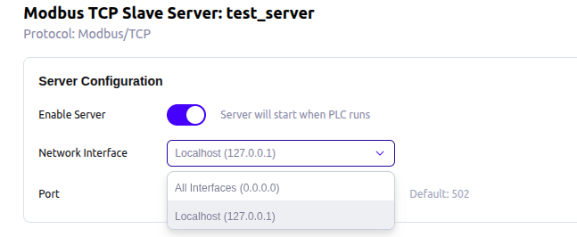
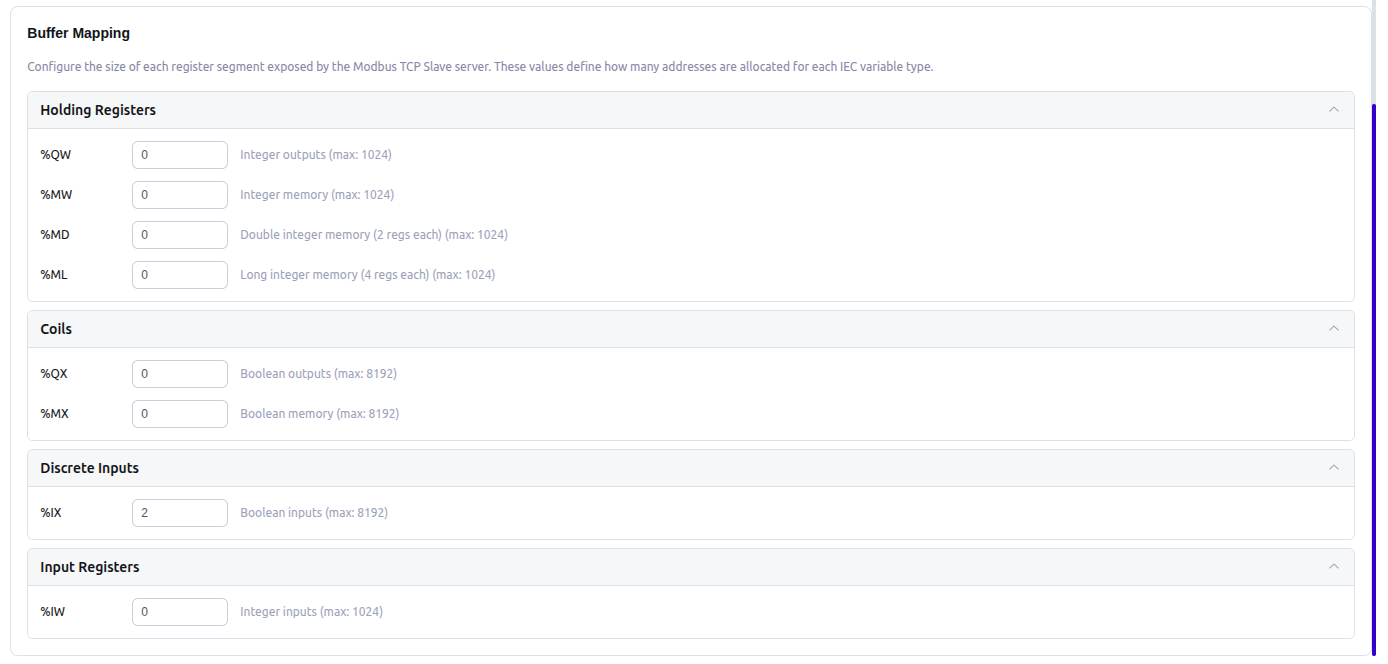
- MODBUS SERVER里除了IX其他都设置为0,即只传输Discrete Input数据(这里是runtime的模拟配置,实际配置可选项根据具体运行硬件环境确定):
| OpenPLC 地址 | 含义 | 常见用途 |
|---|---|---|
%IX0.0 | 输入位 | 数字量输入 DI |
%QX0.0 | 输出位 | 数字量输出 DO |
%IW0 | 输入字 | 模拟量输入等 |
%QW0 | 输出字 | 模拟量输出等 |
%MW0 | 内部字 | PLC 内部整数变量 |
%MD0 | 内部双字 | 32 位整数/实数等 |
%ML0 | 内部长整型 | 64 位相关数据 |
| OpenPLC | Modbus区域 | 数据大小 | 常见功能码 |
|---|---|---|---|
%QX | Coil | 1 bit | 01 / 05 / 15 |
%MX | Coil | 1 bit | 01 / 05 / 15 |
%IX | Discrete Input | 1 bit | 02 |
%QW | Holding Register | 16 bit | 03 / 06 / 16 |
%MW | Holding Register | 16 bit | 03 / 06 / 16 |
%IW | Input Register | 16 bit | 04 |
%MD | Holding Register | 32 bit | 03 / 06 / 16 |
%ML | Holding Register | 64 bit | 03 / 06 / 16 |
PLC 四种编程语言对比
- LAD 是“电路思维”,STL 是“指令思维”,SCL 是“程序思维”。
| 对比项目 | LAD | FBD | STL | SCL |
|---|---|---|---|---|
| 中文名称 | 梯形图 | 功能块图 | 语句表 | 结构化控制语言 |
| 英文全称 | Ladder Logic Diagram | Function Block Diagram | Statement List | Structured Control Language |
| 编程形式 | 触点、线圈 | 功能块、连线 | 指令助记符 | 类似 Pascal 的高级语言 |
| 主要特点 | 直观、像继电器控制 | 图形化、功能块清晰 | 指令级、灵活 | 高级语言、结构化 |
| 逻辑控制 | 非常适合 | 非常适合 | 适合 | 适合 |
| 数学运算 | 一般 | 一般 | 较方便 | 非常适合 |
| 数据处理 | 一般 | 一般 | 较复杂 | 非常适合 |
| 循环/条件判断 | 较麻烦 | 较麻烦 | 可以 | 非常方便 |
| 定时器/计数器 | 直观 | 直观 | 较复杂 | 方便 |
| 调试 | 非常直观 | 直观 | 较困难 | 较方便 |
| 适合初学者 | ★★★★★ | ★★★★☆ | ★★☆☆☆ | ★★★☆☆ |
| 适合复杂算法 | ★★☆☆☆ | ★★★☆☆ | ★★★☆☆ | ★★★★★ |
| 典型应用 | 电机、按钮、联锁 | 顺序控制、功能块 | 老式 STEP 7 程序 | 算法、数据处理、复杂控制 |
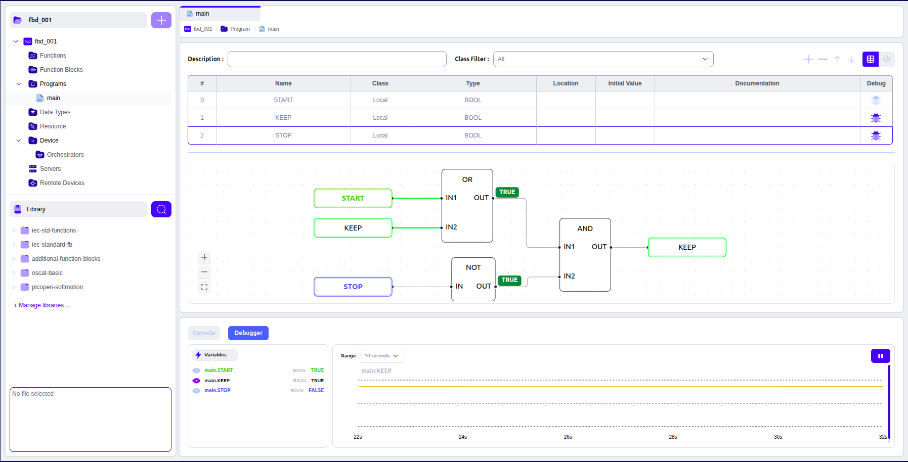
FBD的起保停:
STL 实现起保停:
- Motor = (Start OR Motor) AND NOT Stop
典型 STL 写法:
A     I0.0       // Stop,常闭条件
AN    I0.1       // Start
O     M0.0       // 保持条件
=     M0.0       // 输出/运行状态
不过这里要特别注意 STL 累加器逻辑运算的执行顺序,不能简单把 LAD 的每一根线机械翻译。
更清晰地按照:
Motor = (Start OR Motor) AND NOT Stop
表达,可以写成:
A     I0.1       // Start
O     M0.0       // OR Motor
AN    I0.0       // AND NOT Stop
=     M0.0       // Motor
其中:
| 地址 | 含义 |
|---|---|
I0.1 | 启动按钮 Start |
I0.0 | 停止按钮 Stop |
M0.0 | 电机运行保持位 |
SCL 实现起保停
- SCL 就更加直观:
IF Stop THEN
    Motor := FALSE;
ELSIF Start THEN
    Motor := TRUE;
END_IF;
- 逻辑是:
Stop = 1
    ↓
Motor = 0

Stop = 0 且 Start = 1
    ↓
Motor = 1

Stop = 0 且 Start = 0
    ↓
Motor 保持原状态
- 用更简洁的逻辑表达也可以写成:
Motor := (Motor OR Start) AND NOT Stop;
注意
IF Start THEN
    Motor := TRUE;
END_IF;

IF Stop THEN
    Motor := FALSE;
END_IF;
-
也能实现基本的起保停,但存在一个重要问题:
-
SCL 是顺序执行的。PLC 从上往下执行,Start 和 Stop 同时为 TRUE 时,Stop 后执行,所以 Motor 最终为 FALSE。
-
如果程序顺序反过来:
IF Stop THEN
    Motor := FALSE;
END_IF;

IF Start THEN
    Motor := TRUE;
END_IF;
- 那么 Start 和 Stop 同时为 TRUE 时,最终反而是:
Motor = TRUE
- 因此工程上通常明确规定停止优先:
IF Stop THEN
    Motor := FALSE;
ELSIF Start THEN
    Motor := TRUE;
END_IF;
- 这样:
Stop 优先级 > Start
- 更加安全、清晰。
常见的工程控制原则
| 原则 | 含义 | 典型例子 |
|---|---|---|
| 停止优先 | 启动和停止同时出现时,优先停止 | Start + Stop 同时按下 → 电机不运行 |
| 复位优先 | Set 和 Reset 同时出现时,优先 Reset | 启动条件和复位条件同时出现 → 保持复位 |
| 故障优先 | 正常运行和故障同时出现时,故障优先 | 电机运行过程中检测到故障 → 立即停止 |
| 安全优先 | 安全条件不满足时,不允许设备动作 | 安全门打开 → 禁止启动 |
| 互锁优先 | 两个互斥动作同时请求时,禁止同时动作 | 正转、反转不能同时输出 |
| 手动优先 | 手动操作时屏蔽自动控制 | 自动运行过程中切换手动 → 自动命令不再控制输出 |
| 急停优先 | 急停信号具有最高优先级 | 急停 → 所有相关运行输出立即关闭 |
| 断电安全 | 控制电源/信号丢失时趋向安全状态 | 运行许可丢失 → 电机停止 |
| 防重复启动 | 已经运行时,重复启动命令不起作用 | 电机已经运行,再按 Start 不重新执行启动流程 |
| 防误动作 | 条件不完整时禁止动作 | 气缸未回原位 → 禁止启动下一步 |
| 状态优先 | 当前设备状态限制某些命令 | 电机运行中禁止改变某些参数 |
| 故障锁存 | 故障发生后保持故障状态,直到人工复位 | 过载 → Fault 保持,Reset 后解除 |
OPENPLC的项目结构
-
OpenPLC主要由https://github.com/Autonomy-Logic/openplc-editor和https://github.com/Autonomy-Logic/openplc-runtime组成。
-
OpenPLC Editor v4的流程:PLC program→JSON → XML → ST → C(
https://github.com/Autonomy-Logic/openplc-runtime/blob/main/docs/COMPILATION_FLOW.md) -
然后以上的C代码编译为一个new_libplc.so文件链接到运行时
https://github.com/Autonomy-Logic/openplc-runtime/blob/main/docs/ARCHITECTURE.md
openplc-runtime/
├── webserver/              # Flask REST API server
│   ├── app.py             # Main application entry
│   ├── restapi.py         # REST API blueprint
│   ├── debug_websocket.py # WebSocket debug interface
│   ├── unixclient.py      # Unix socket client
│   ├── plcapp_management.py # Build orchestration
│   ├── runtimemanager.py  # Runtime process control
│   ├── credentials.py     # TLS certificate generation
│   └── config.py          # Configuration management
├── core/
│   ├── src/plc_app/       # PLC runtime source
│   │   ├── plc_main.c     # Main entry point
│   │   ├── plc_state_manager.cpp/h # State management
│   │   ├── unix_socket.c/h # IPC server
│   │   ├── debug_handler.c/h # Debug protocol
│   │   └── utils/         # Utilities (log, watchdog, timing)
│   ├── src/drivers/       # Plugin driver system
│   └── generated/         # Generated PLC code (runtime)
├── scripts/               # Build and management scripts
│   ├── compile.sh         # Compile PLC program
│   ├── compile-clean.sh   # Clean and rename library
│   └── manage_plugin_venvs.sh # Plugin venv management
├── build/                 # Compilation output
│   ├── plc_main           # Compiled runtime executable
│   └── libplc_*.so        # Compiled PLC program libraries
└── venvs/                 # Python virtual environments
    ├── runtime/           # Web server venv
    └── {plugin_name}/     # Per-plugin venvs
//-----------------------------------------------------------------------------
// Copyright 2018 Thiago Alves
// This file is part of the OpenPLC Runtime.
//
// OpenPLC is free software: you can redistribute it and/or modify
// it under the terms of the GNU General Public License as published by
// the Free Software Foundation, either version 3 of the License, or
// (at your option) any later version.
//
// OpenPLC is distributed in the hope that it will be useful,
// but WITHOUT ANY WARRANTY; without even the implied warranty of
// MERCHANTABILITY or FITNESS FOR A PARTICULAR PURPOSE.  See the
// GNU General Public License for more details.
//
// You should have received a copy of the GNU General Public License
// along with OpenPLC.  If not, see <http://www.gnu.org/licenses/>.
//------
//
// This is the main file for the OpenPLC. It contains the initialization
// procedures for the hardware, network and the main loop
// Thiago Alves, Jun 2018
//-----------------------------------------------------------------------------

#include <stdio.h>
#include <string.h>
#include <pthread.h>
#include <time.h>
#include <signal.h>
#include <stdlib.h>
#include <unistd.h>
#include <stdint.h>
#include <sys/mman.h>

#include "iec_types.h"
#include "ladder.h"
#ifdef _ethercat_src
#include "ethercat_src.h"
#endif

#include "oplc_snap7.h"

#define OPLC_CYCLE          50000000

extern int opterr;
IEC_BOOL __DEBUG;

unsigned long __tick = 0;
pthread_mutex_t bufferLock; //mutex for the internal buffers
uint8_t run_openplc = 1; //Variable to control OpenPLC Runtime execution

// pointers to IO *array[const][const] from cpp to c and back again don't work as expected, so instead callbacks
uint8_t *bool_input_call_back(int a, int b){ return bool_input[a][b]; }
uint8_t *bool_output_call_back(int a, int b){ return bool_output[a][b]; }
uint8_t *byte_input_call_back(int a){ return byte_input[a]; }
uint8_t *byte_output_call_back(int a){ return byte_output[a]; }
uint16_t *int_input_call_back(int a){ return int_input[a]; }
uint16_t *int_output_call_back(int a){ return int_output[a]; }
uint32_t *dint_input_call_back(int a){ return dint_input[a]; }
uint32_t *dint_output_call_back(int a){ return dint_output[a]; }
uint64_t *lint_input_call_back(int a){ return lint_input[a]; }
uint64_t *lint_output_call_back(int a){ return lint_output[a]; }
void logger_callback(char *msg){ openplc_log(msg);}

int main(int argc,char **argv)
{
    // Define the max/min/avg/total cycle and latency variables used in REAL-TIME computation(in nanoseconds)
    long cycle_avg, cycle_max, cycle_min, cycle_total;
    long latency_avg, latency_max, latency_min, latency_total;
    cycle_max = 0;
    cycle_min = LONG_MAX;
    cycle_total = 0;
    latency_max = 0;
    latency_min = LONG_MAX;
    latency_total = 0;

    char log_msg[1000];
    sprintf(log_msg, "OpenPLC Runtime starting...\n");
    openplc_log(log_msg);

    //======================================================
    //                 PLC INITIALIZATION
    //======================================================
    tzset();
    time(&start_time);
    pthread_t interactive_thread;
    pthread_create(&interactive_thread, NULL, interactiveServerThread, NULL);
    config_init__();
    glueVars();

    //======================================================
    //               MUTEX INITIALIZATION
    //======================================================
    if (pthread_mutex_init(&bufferLock, NULL) != 0)
    {
        printf("Mutex init failed\n");
        exit(1);
    }

    //======================================================
    //              HARDWARE INITIALIZATION
    //======================================================
#ifdef _ethercat_src
    type_logger_callback logger = logger_callback;
    ethercat_configure("../utils/ethercat_src/build/ethercat.cfg", logger);
#endif
    initializeHardware();
    initializeMB();

    updateBuffersIn();
    updateBuffersOut();

    //======================================================
    //          PERSISTENT STORAGE INITIALIZATION
    //======================================================
    glueVars();
    mapUnusedIO();
    readPersistentStorage();
    //pthread_t persistentThread;
    //pthread_create(&persistentThread, NULL, persistentStorage, NULL);

    //======================================================
    //            S7 PROTOCOL INITIALIZATION
    //======================================================
    initializeSnap7();


#ifdef __linux__
    //======================================================
    //              REAL-TIME INITIALIZATION
    //======================================================
    // Set our thread to real time priority
    struct sched_param sp;
    sp.sched_priority = 30;
    printf("Setting main thread priority to RT\n");
    if(pthread_setschedparam(pthread_self(), SCHED_FIFO, &sp))
    {
        printf("WARNING: Failed to set main thread to real-time priority\n");
    }

    // Lock memory to ensure no swapping is done.
    printf("Locking main thread memory\n");
    if(mlockall(MCL_FUTURE|MCL_CURRENT))
    {
        printf("WARNING: Failed to lock memory\n");
    }
#endif

    // Define the start, end, cycle time and latency time variables
    struct timespec cycle_start, cycle_end, cycle_time;
    struct timespec timer_start, timer_end, sleep_latency;

    //gets the starting point for the clock
    printf("Getting current time\n");
    clock_gettime(CLOCK_MONOTONIC, &timer_start);

    //======================================================
    //                    MAIN LOOP
    //======================================================
    while(run_openplc)
    {
        // Get the start time for the running cycle
        clock_gettime(CLOCK_MONOTONIC, &cycle_start);

        //make sure the buffer pointers are correct and
        //attached to the user variables
        glueVars();

#ifdef _ethercat_src
        boolvar_call_back bool_input_callback = bool_input_call_back;
        boolvar_call_back bool_output_callback = bool_output_call_back;
        int8var_call_back byte_input_callback = byte_input_call_back;
        int8var_call_back byte_output_callback = byte_output_call_back;
        int16var_call_back int_input_callback = int_input_call_back;
        int16var_call_back int_output_callback = int_output_call_back;
        int32var_call_back dint_input_callback = dint_input_call_back;
        int32var_call_back dint_output_callback = dint_output_call_back;
        int64var_call_back lint_input_callback = lint_input_call_back;
        int64var_call_back lint_output_callback = lint_output_call_back;
#endif

        updateBuffersIn(); //read input image

        pthread_mutex_lock(&bufferLock); //lock mutex


#ifdef _ethercat_src
        if(ethercat_callcyclic(BUFFER_SIZE,
                bool_input_callback,
                bool_output_callback,
                byte_input_callback,
                byte_output_callback,
                int_input_callback,
                int_output_callback,
                dint_input_call_back,
                dint_output_call_back,
                lint_input_call_back,
                lint_output_call_back)){
            printf("EtherCAT cyclic failed\n");
            break;
        }
#endif
        updateBuffersIn_MB(); //update input image table with data from slave devices
        handleSpecialFunctions();
        config_run__(__tick++); // execute plc program logic
        updateBuffersOut_MB(); //update slave devices with data from the output image table
        pthread_mutex_unlock(&bufferLock); //unlock mutex

        updateBuffersOut(); //write output image

        updateTime();

        // Get the end time for the running cycle
        clock_gettime(CLOCK_MONOTONIC, &cycle_end);
        // Compute the time usage in one cycle and do max/min/total comparison/recording
        timespec_diff(&cycle_end, &cycle_start, &cycle_time);
        if (cycle_time.tv_nsec > cycle_max)
            cycle_max = cycle_time.tv_nsec;
        if (cycle_time.tv_nsec < cycle_min)
            cycle_min = cycle_time.tv_nsec;
        cycle_total = cycle_total + cycle_time.tv_nsec;

        sleep_until(&timer_start, common_ticktime__);

        // Get the sleep end point which is also the start time/point of the next cycle
        clock_gettime(CLOCK_MONOTONIC, &timer_end);
        // Compute the time latency of the next cycle(caused by sleep) and do max/min/total comparison/recording
        timespec_diff(&timer_end, &timer_start, &sleep_latency);
        if (sleep_latency.tv_nsec > latency_max)
            latency_max = sleep_latency.tv_nsec;
        if (sleep_latency.tv_nsec < latency_min)
            latency_min = sleep_latency.tv_nsec;
        latency_total = latency_total + sleep_latency.tv_nsec;

        // Store the cycle_time/sleep_latency in microsecond, so it can be displayed in the webpage
        RecordCycletimeLatency((long)cycle_time.tv_nsec / 1000, (long)sleep_latency.tv_nsec / 1000);
    }

    // Compute/print the max/min/avg cycle time and latency
    cycle_avg = (long)cycle_total / __tick;
    latency_avg = (long)latency_total / __tick;
    printf("###Summary: The maximum/minimum/average cycle time in microsecond is %ld/%ld/%ld\n",
    cycle_max / 1000, cycle_min / 1000, cycle_avg / 1000);
    printf("###Summary: The maximum/minimum/average latency in microsecond is %ld/%ld/%ld\n",
    latency_max / 1000,   latency_min / 1000, latency_avg / 1000);

    //======================================================
    //             SHUTTING DOWN OPENPLC RUNTIME
    //======================================================
    pthread_join(interactive_thread, NULL);
#ifdef _ethercat_src
    ethercat_terminate_src();
#endif

    finalizeSnap7();
    printf("Disabling outputs\n");
    disableOutputs();
    updateBuffersOut();
    finalizeHardware();
    printf("Shutting down OpenPLC Runtime...\n");
    exit(0);
}
CG
-
Beremiz is Free Software for machine automation.:Beremiz is an integrated development environment for machine automation. It is Free Software, conforming to IEC-61131 among other standards.
-
OpenPLC Editor - IDE capable of creating programs for the OpenPLC Runtime
-
Developer Docs v3: https://openplcproject.gitlab.io/openplc_v3/md_README.html
-
https://edge.autonomylogic.com/docs/openplc-editor/communication/modbus/server
-
PLC工程师只会梯形图编程真的落后了吗?实际上ST、SCL编程比梯形图编程简单多了,掌握if_else_for三条指令可以干遍天下无敌
-
与电路图的网络不同,电气图用“线号 + 端子号 + 页码/位置”把整个电气连接关系串起来。
-
学过电气识图的人学 LAD 往往比较快:他已经习惯了通过设备代号、触点、线号、端子号追踪整个控制回路。
-
电工与电子技术基础 9787121303906


 扫一扫
扫一扫


 1181
1181

 被折叠的 条评论
为什么被折叠?
被折叠的 条评论
为什么被折叠?
 到【灌水乐园】发言


