


提示:文章写完后,目录可以自动生成,如何生成可参考右边的帮助文档
前言
本文记录了使用logicFlow绘制流程图时的一些重要步骤和流程。
`
一、命令安装
命令安装
通过使用 npm、yarn、pnpm 进行安装。
npm install @logicflow/core --save
# 插件包(不使用插件时不需要引入)
npm install @logicflow/extension --save
二、引入
1.引入库
代码如下(示例):
<script>
  import LogicFlow from "@logicflow/core";
  import "@logicflow/core/lib/style/index.css";
  // import "@logicflow/core/dist/style/index.css"; // 2.0版本前的引入方式
2.节点数据和边数据以及初始化流程图容器
代码如下(示例):
const theme={
  rect: {
    fill: "#409eff",//矩形的填充背景色
    // strokeDasharray: "10, 1",
    // className: "custom-cls",
    radius: 30//矩形圆角
  },
  nodeText:{//节点文字样式
    color:'#fff'
  },
  edgeText: {//边文字样式
    // textWidth: 60,
    // overflowMode: "autoWrap",
    color:'#000'
    // background: {
    //   fill: "#919810"
    // }
  },
}
//绘制流程图
const init=(data:any)=>{
  const lf = new LogicFlow({
        container: drawContiner.value,
        grid: false,
        stopScrollGraph: true, // 禁止鼠标滚动移动画布
        stopMoveGraph: true, // 禁止拖动画布
        stopZoomGraph: true,// 禁止缩放
        isSilentMode :true,
        style:theme,//自定义画布一些样式属性
      });
      lf.clearData()
      lf.render(data);//渲染节点和边数据
}
设置节点数据
//流程图logicFlow节点
const nodes:any=ref([

])
//监听窗口变化,绘制流程图
window.addEventListener('resize',function(){
    initNode()
})
//节点 大小
const nodeWidth=ref(100)
const nodeHeight=ref(50)
const smallNodeWidth=ref(100)
const smallNodeHeight=ref(50)
//流程图节点赋值
const initNode=()=>{
    //按节点数进行节点位置设置
  totalWidth.value=drawContiner.value.offsetWidth//画布宽度
  let xData=totalWidth.value/(flowData.value.length+1)//每个节点所占的宽度
  console.log(xData,totalWidth.value,flowData.value.length)
  //审批节点大小
  nodeWidth.value=120*(totalWidth.value/1150)>120?120*(totalWidth.value/1150):120//根据窗口改变节点的大小
  nodeHeight.value=50*(totalWidth.value/1150)>50?50*(totalWidth.value/1150):50
  //开始结束节点大小
  smallNodeWidth.value=100*(totalWidth.value/1150)>100?100*(totalWidth.value/1150):100
  smallNodeHeight.value=50*(totalWidth.value/1150)>50?50*(totalWidth.value/1150):50
//绘制前先清空
nodes.value=[]
//开始节点和送审节点
  nodes.value.push({
    id:'node0',
    type:'rect',
    x: xData/2,
    y: 50,
    width: 100,
    height: 50,
    text: '开始',
    properties: {
        // statu: 'pass', // 业务属性
        width: smallNodeWidth.value, // 大于80再根据窗口大小变化
        height: smallNodeHeight.value,
        radius: 5,
        style: {
          // 样式属性
          strokeWidth: 2,
          stroke:'#67C23A',
          fill:'rgb(135, 211, 123)'
        },
      },

  })
//添加流程节点
  flowData.value.forEach((item:any,index:any)=>{
    const node={
          id: 'node'+(index+1),
          type: 'rect',
          x: xData*(index+1)+xData/2,
          y: 125*(index+1),
          text: '审批',
          properties: {
        width: nodeWidth.value, // 形状属性
        height: nodeHeight.value,
        // shadow:{
        //     color: 'rgba(0, 0, 0, 0.5)',
        //   blur: 10,
        //   offsetX: 5,
        //   offsetY: 5,
        // },
        boxShadow: '4px 4px 10px rgba(0, 0, 0, 0.3)', // 添加阴影
        radius: 5,
        style: {
          // 样式属性
          strokeWidth: 2,
          stroke: '#409eff',  // 边框颜色
          fill:'rgb(129, 190, 255)',
          shadowColor: 'rgba(0, 0, 0, 0.3)', // 阴影颜色
        shadowBlur: 10, // 阴影模糊程度
        shadowOffsetX: 5, // 阴影相对于物体的X轴偏移量
        shadowOffsetY: 5, // 阴影相对于物体的Y轴偏移量
            // lineWidth: 20,  // 边框宽度
          // fill:'green'
        },
      },
        }
        nodes.value.push(node)
        // lf.addNode(node)
  })
//添加结束节点
  nodes.value.push({
    id: 'node'+nodes.value.length,
          type: 'rect',
          x: xData*(nodes.value.length-1)+xData/2,
          y: 125*(nodes.value.length),
          text: '结束',
          properties: {
        width: smallNodeWidth.value, // 形状属性
        height: smallNodeHeight.value,
        radius: 5,
        style: {
          // 样式属性
          strokeWidth: 2,
          stroke:'#F56C6C',
          fill:'rgb(254, 163, 163)'
        },
      },
  })
  console.log(nodes.value)
//设置连接线
initEdge()
//     const data={nodes:nodes.value,edges:edges.value}
//     console.log(data)
//   init(data)
//   drawContiner.value.style.height = `${150*(nodes.value.length)}px`;
}
设置边数据以及如何设置连接锚点
//设置连接线
//设置连接线
const initEdge=()=>{
    totalWidth.value=drawContiner.value.offsetWidth
    let xData=totalWidth.value/(flowData.value.length+1)
//添加节点之间的连线
    //先清空连接线
    edges.value=[]
    //连接开始和送审节点
    edges.value.push({
          id: 'egdeS',
          sourceNodeId: 'node0',
          targetNodeId: 'node1',
          type: 'polyline',
          startPoint: {
            x:xData/2,
            y: 50+smallNodeHeight.value/2,
            },
            endPoint: {
                x: xData+xData/2-nodeWidth.value/2,
                y: 125,
            },
            pointsList: [
            {
                x:xData/2,
                y:50+smallNodeHeight.value/2,
            },
            {
                x:xData/2,
                y:  125,
            },
            {
                x: xData+xData/2-nodeWidth.value/2,
                y: 125,
            },
            ],
          properties: {
            style:{
              stroke:'green'
            }
          },
          text: '送审',
    }),
    //连接流程节点之间的连线
  flowData.value.forEach((item:any,index:any)=>{
  //第一个节点驳回连线直接连接结束节点
    if(item.returnFlag=='1'&&index<1&&flowData.value.length>1){
        const edge={
        id: 'edgeb'+index,
        sourceNodeId: 'node'+(index+1),
        targetNodeId: 'node'+(nodes.value.length-1),
        startPoint: {//连线起点
            x:xData*(index+1)+xData/2,
            y: 125*(index+1)+nodeHeight.value/2,
            },
            endPoint: {//连线终点
            //   x: xData*(index)+100+60,
              x:xData*(nodes.value.length-2)+xData/2-smallNodeWidth.value/2,
              y: 125*(nodes.value.length-1),
            },
            pointsList: [
            {
                x:xData*(index+1)+xData/2,
            y: 125*(index+1)+nodeHeight.value/2,
            },
              {//连线转折点
                x:xData*(index+1)+xData/2,
                y: 125*(nodes.value.length-1),
              },
              // {
              //   x:xData*(index),
              //   y: 150*(index+1),
              // },
              {
                x:xData*(nodes.value.length-2)+xData/2-smallNodeWidth.value/2,
              y: 125*(nodes.value.length-1),
            },
            ],
        properties: {
        style:{
            stroke:'red'
            }
        },
        type: 'polyline',
        text: '驳回',
    }
    edges.value.push(edge)
    }
    if(item.returnFlag=='1'&&index>=1){//逐级驳回连线
    const edge={
        id: 'edgeb'+index,
        sourceNodeId: 'node'+(index+1),
        targetNodeId: 'node'+(index+0),
        startPoint: {//连线起点
            x:xData*(index+1)+xData/2-nodeWidth.value/2,
            y: 125*(index+1)-nodeHeight.value/2,
            },
            endPoint: {//连线终点
            //   x: xData*(index)+100+60,
              x:xData*(index)+xData/2+nodeWidth.value/2,
              y: 125*(index),
            },
            pointsList: [
            {
                x:xData*(index+1)+xData/2,
            y: 125*(index+1)-smallNodeHeight.value/2,
            },
              {//连线转折点
                x:xData*(index+1)+xData/2,
                y: 125*(index),
              },
              // {
              //   x:xData*(index),
              //   y: 150*(index+1),
              // },
              {
                x:xData*(index)+xData/2+nodeWidth.value/2,
                y: 125*(index),
            },
            ],
        properties: {
        style:{
            stroke:'red'
            }
        },
        type: 'polyline',
        text: '驳回',
    }
    edges.value.push(edge)
  }
    if(index+1==flowData.value.length){//最后一个节点和结束节点之间的联系
        const edge={
            id: 'edge'+index,
            sourceNodeId: 'node'+(index+1),
            targetNodeId: 'node'+(index+2),
            type: 'polyline',
            text: '通过/驳回',
            properties: {
            style:{
                stroke:'green'
            }
            },
    }
    edges.value.push(edge)
    // lf.addEdge(edge)
    }else{//其它连线(审批通过连线)
    const edge={
        id: 'edge'+index,
        sourceNodeId: 'node'+(index+1),
        targetNodeId: 'node'+(index+2),
        type: 'polyline',
        text: '通过',
        startPoint: {
            x:xData*(index+1)+xData/2,
            y:125*(index+1)+nodeHeight.value/2,
            },
            endPoint: {
              x: xData*(index+2)+xData/2-nodeWidth.value/2,
              y: 125*(index+1),
            },
            pointsList: [
            {
            x:xData*(index+1)+xData/2,
            y: 125*(index+1)+nodeHeight.value/2,
            },
              {
                x:xData*(index+1)+xData/2,
                y: 125*(index+2),
              },
              // {
              //   x:xData*(index),
              //   y: 150*(index+1),
              // },
              {
                x: xData*(index+2)+xData/2-nodeWidth.value/2,
              y: 125*(index+2),
            },
            ],
        properties: {
        style:{
            stroke:'green'
            }
          },
    }
    edges.value.push(edge)
    // lf.addEdge(edge)
    }

  })
  console.log(edges.value)
  let data={nodes:nodes.value,edges:edges.value}
    console.log(data)
    nextTick(()=>{
        if(flowData.value.length>0){
            init(data)
        }else{
            data={nodes:[],edges:[]}
            init(data)
        }
    })
//   根据流程节点数调整画布高度
  drawContiner.value.style.height = `${125*(nodes.value.length)}px`;
}
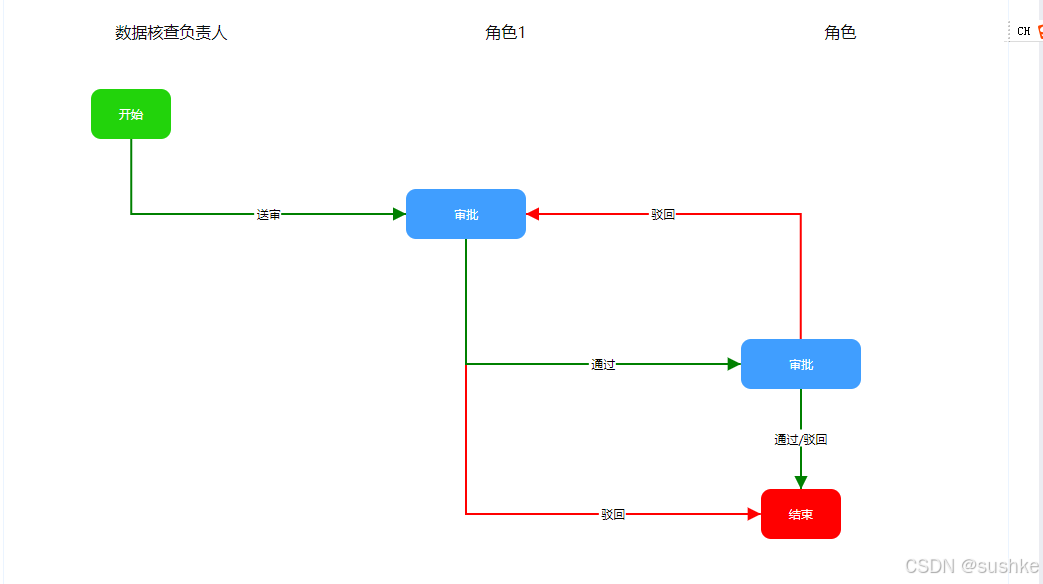
流程图效果
总结
以上就是今天要讲的内容,关于logicFlow的初始化,容器设置,样式设置,以及节点的设置和边的设置,以及边的锚点的设置。
重点:如何设置连接锚点
需设置起始锚点,终点和转折点,这几个点通常和起始节点和终点节点的坐标有关。
比如起始节点的
上方锚点的横坐标为起始节点的横坐标,纵坐标为起始节点纵坐标减掉起始节点的高度的一半
下方锚点的横坐标为起始节点的横坐标,纵坐标为起始节点纵坐标加上起始节点的高度的一半
左边锚点的横坐标为起始节点的横坐标减掉节点的宽度的一半,纵坐标为起始节点纵坐标
右边锚点的横坐标为起始节点的横坐标加上节点的宽度的一半,纵坐标为起始节点纵坐标
终点坐标同理
转折点坐标一般横坐标为起始锚点的横坐标,纵坐标为终点锚点的纵坐标
 startPoint: {//起始点,用于自定义起始锚点,而不是用默认锚点
            x:xData/2-40,//起始节点的下方锚点横坐标,(就是起始节点横坐标)
            y: 50+25,//起始节点的下方锚点纵坐标(起始节点纵坐标加上起始节点高度的一半)
            },
            endPoint: {//终点,用于自定义终点锚点,而不是用默认锚点
                x: xData+xData/2-40-60,
                y: 150,
            },
            pointsList: [
            {//起始锚点,跟上边起始点锚点坐标一样
                x:xData/2-40,
                y: 50+25,
            },
            {//转折点,折线的转折点坐标,
                x:xData/2-40,
                y:  150,
            },
            {//终点锚点跟上边终点锚点坐标一样
                x: xData+xData/2-40-60,
                y: 150,
            },
            ],


 扫一扫
扫一扫


 2618
2618

 被折叠的 条评论
为什么被折叠?
被折叠的 条评论
为什么被折叠?
 到【灌水乐园】发言


